|
应用规范
1、 设计制造:API602;
2、 结构长度:按ASME/ANSI B16.10;JB/T97-95
3、 连接端尺寸:1)法兰端尺寸按ANSI B16.5;JB79
2)承插口尺寸按ANSI B16.11;JB/T1751
3)螺纹端尺寸按ANSI B1.20.1;JB/T73.6
4)对焊端尺寸按ANSI B16.25;JB/T12224
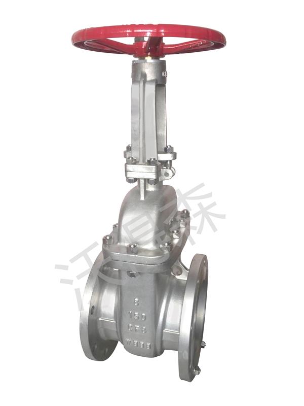
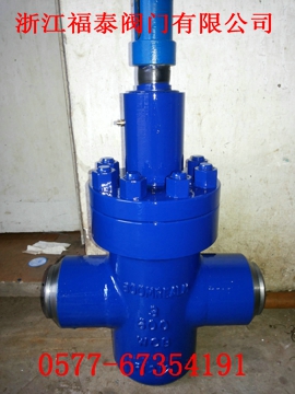
4、 结构特征:螺栓连接阀盖(B.B)和明杆支架(OS&Y)或焊接阀盖(W.B)和明杆支架(OS&Y)
5、 主体材料:A105;LF2;F11;F22;F304;F316;F321;F51;Monel;20合金等
6、 阀门检验和试验:API598;GB/T13927;JB/T9092
Applied norm
1. Design and manufacture: API602
2. Ends connection:
1)Dimension of flange: ANSI B16.5;JB79
2)SW dimension: ANSI B16.11;JB/T1751
3)Screwed dimension: ANSI B1.20.1;JB/T73.6
4)BW dimension: ANSI B16.25;JB/T12224
3. Structural feature:Bolt bonnet(BB) and outside screwed
and yoke(OS&Y).or welded bonnet(W.B)
and outside screwed and yoke(OS&Y)
4. Body material: A105;LF2;F11;F22;F304;F316;F321;F51;Monel;20#alloy
5. Valve inspection and test :API598;GB/T13927;JB/T9092
主要尺寸和重量 Main dimensions and weight
|
规格 |
R.P |
(mm) |
8 |
10 |
15 |
20 |
25 |
32 |
40 |
50 |
- |
|
(in.) |
1/4 |
3/8 |
1/2 |
3/4 |
1 |
11/4 |
11/2 |
2 |
- |
|
F.P |
(mm) |
- |
8 |
10 |
15 |
20 |
25 |
32 |
40 |
50 |
|
(in.) |
- |
1/4 |
3/8 |
1/2 |
3/4 |
1 |
11/4 |
11/2 |
2 |
|
D |
R.P |
7 |
10 |
10 |
13 |
18 |
24 |
29 |
36.5 |
- |
|
F.P |
- |
7 |
10 |
13 |
18 |
24 |
29 |
36.5 |
46.5 |
|
L |
R.P |
79 |
79 |
79 |
92 |
111 |
120 |
120 |
140 |
- |
|
F.P |
- |
79 |
79 |
92 |
111 |
120 |
120 |
140 |
178 |
|
H(开启)(Open) |
R.P |
149 |
158 |
158 |
169 |
197 |
236 |
246 |
283 |
- |
|
F.P |
- |
158 |
158 |
169 |
197 |
236 |
246 |
283 |
330 |
|
W |
R.P |
100 |
100 |
100 |
100 |
125 |
160 |
160 |
180 |
- |
|
F.P |
- |
100 |
100 |
100 |
125 |
160 |
160 |
180 |
200 |
|
重量(Kg)
Weight |
R.P |
2.1 |
2.1 |
2.0 |
2.3 |
4.3 |
5.9 |
6.9 |
11.1 |
- |
|
F.P |
- |
2.0 |
2.3 |
4.3 |
5.9 |
6.9 |
69 |
15.2 |
- |
说明:1.体盖焊接结构(W.B)闸阀,在阀门类型“Z”代号前冠以符号“H”表示,例如:HZ61H-800;
中法兰螺栓结构“B.B”代号“略”,例如:Z61H-800。
Notes:1.Welded bonnet structure gate valve,marked with H in front of the valve type Z,for example,HZ61H-800.
The code of the flange bolt structure “B.B” default,for example Z61H-800. | 


